Abstract
Tapered roller bearings are a class of rolling-element bearings engineered with conical rollers guided by a flanged inner ring. Their unique geometry, featuring tapered inner and outer ring raceways, allows them to accommodate substantial combined loads, meaning both radial and axial forces simultaneously. The principle of operation hinges on the angled contact between the rollers and raceways, which resolves applied forces into their respective radial and axial components. This design imparts high load-carrying capacity and operational rigidity, making these bearings indispensable in demanding applications. Industries heavily reliant on them include automotive for wheel hubs and transmissions, heavy industrial machinery for gearboxes and rolling mills, and aerospace for landing gear systems. The selection, mounting, and maintenance of tapered roller bearings are pivotal for ensuring machinery longevity and performance. Proper preload application is a distinguishing feature of their installation, directly influencing stiffness, operational life, and rotational accuracy. As of 2025, advancements continue in materials science and integrated sensor technology, further enhancing their reliability and performance in an increasingly connected industrial landscape.
Key Takeaways
- Their unique conical design handles both radial and axial forces at the same time.
- Properly setting the preload during installation is vital for bearing life and performance.
- Tapered roller bearings are essential for automotive, industrial, and heavy machinery.
- Different configurations like single, double, or four-row serve specific load needs.
- Correct lubrication and maintenance prevent most common causes of premature failure.
- Material choice, like case-hardened steel, determines durability under heavy loads.
- Always match the bearing’s load ratings and speed limits to your application’s demands.
Table of Contents
- Insight 1: The Foundational Geometry – Why Tapered Design Excels
- Insight 2: Material Science and Manufacturing – The Heart of Durability
- Insight 3: Mastering the Configurations – Single, Double, and Four-Row Bearings
- Insight 4: The Art of Selection – Matching the Bearing to the Application
- Insight 5: Installation and Mounting – Precision is Paramount
- Insight 6: Lubrication and Maintenance – The Lifeline of a Bearing
- Insight 7: The Future of Bearing Technology – Trends and Innovations for 2025 and Beyond
Insight 1: The Foundational Geometry – Why Tapered Design Excels
To truly grasp the capability of a tapered roller bearing, one must first appreciate the elegance of its geometry. Imagine trying to roll a perfect cylinder along a flat path—it moves straight. Now, picture rolling a cone. It naturally traces a circular path. The design of a tapered roller bearing masterfully combines these principles. It consists of four primary components working in concert: the inner ring (cone), the outer ring (cup), the tapered rollers themselves, and a cage to maintain the rollers’ spacing and alignment.
The surfaces of the cone, cup, and rollers are all sections of a larger cone whose apexes converge at a single point on the bearing’s axis. This geometric arrangement is not accidental; it is the very source of the bearing’s strength. When forces are applied, they are distributed along the angled contact surfaces of the rollers and raceways. This design ensures pure rolling motion, minimizing the sliding friction that can generate heat and cause premature wear in other bearing types under combined loads.
The Anatomy of a Tapered Roller Bearing: Cone, Cup, Rollers, and Cage
Let’s break down the components as if we were disassembling a small, intricate machine.
- The Cone (Inner Ring): This is the inner component that fits onto the shaft. It has a tapered raceway on its outer surface upon which the rollers ride. A flange, known as the large rib, at the wider end of the cone guides the rollers and counteracts the axial force component, preventing the rollers from being pushed out.
- The Cup (Outer Ring): This is the outer component that typically fits into a housing. Its inner surface is a tapered raceway that mates with the rollers. Unlike the cone, the cup is usually simpler in form, acting as the outer boundary for the rolling elements.
- The Tapered Rollers: These are the load-carrying elements. Their conical shape allows them to handle the combination of forces. The size, angle, and number of rollers are carefully engineered to provide a specific load capacity and performance profile.
- The Cage (Retainer): The cage is a separator that holds the rollers in their correct positions relative to one another. It ensures they do not bunch up, which would create friction and uneven load distribution. Cages can be made from stamped steel, which is common and cost-effective, or from polyamide for applications requiring lower friction or higher speeds.
Because the cone assembly (cone, rollers, cage) and the cup are separable, mounting becomes more flexible. You can mount the cone assembly on a shaft and the cup in a housing independently, then bring them together during final assembly. This separability is a significant practical advantage in many industrial settings.
The Physics of Force Distribution: Handling Radial and Axial Loads Simultaneously
The genius of the tapered roller bearing lies in how it manages forces. A radial load is a force perpendicular to the shaft, like the weight of a vehicle pressing down on its axle. An axial load (or thrust load) is a force parallel to the shaft, like the force pushing on a propeller.
In a standard ball bearing, these forces are handled differently. Deep groove ball bearings can take some of both, but they are not optimized for heavy axial loads. A dedicated thrust bearing can take immense axial load but almost no radial load. The tapered roller bearing, however, is a master of both.
When a radial load is applied, the tapered shape of the rollers and raceways resolves that force into two components: a normal force (perpendicular to the raceway) and an induced axial force. The bearing is designed to handle the normal force, and the induced axial force is a byproduct that must be managed. For this reason, single-row tapered roller bearings are almost always used in pairs, mounted in opposition to each other. One bearing counteracts the induced axial load of the other. This pairing creates an extremely rigid system capable of supporting heavy loads from any direction.
The angle of the tapered rollers, known as the contact angle, is a determining factor. A steeper contact angle gives the bearing a higher axial load capacity, while a shallower angle prioritizes radial load capacity. Manufacturers design different series of bearings with varying angles to suit specific application needs, from the wheel hubs of passenger cars to the massive gear drives in wind turbines.
A Comparative Look: Tapered Roller Bearings vs. Cylindrical and Ball Bearings
Choosing the right bearing is a matter of understanding the specific demands of a machine. Putting the wrong bearing in a high-load application is like asking a sprinter to lift weights—they might manage for a bit, but failure is inevitable. Let’s compare tapered roller bearings with two other common types: cylindrical roller bearings and deep groove ball bearings.
| Bearing Type | Primary Load Capacity | Misalignment Tolerance | Speed Capability | Rigidity |
|---|---|---|---|---|
| Tapered Roller Bearing | Combined Radial & Axial | Low | Moderate | Very High |
| Cylindrical Roller Bearing | High Radial, Low Axial | Very Low | High | High |
| Deep Groove Ball Bearing | Moderate Radial & Axial | Low to Moderate | Very High | Moderate |
| Spherical Roller Bearing | High Radial, Moderate Axial | High | Moderate | High |
As the table illustrates, each bearing has its domain. Deep groove ball bearings are excellent for high-speed applications with relatively light loads, like small electric motors or household appliances. Their point contact (the ball touches the raceway at a very small point) allows for low friction and high rotational speed, but it also limits their load-carrying capacity.
Cylindrical roller bearings excel where immense radial loads are present, such as in industrial gearboxes or construction machinery. Their line contact (the cylinder touches the raceway along a line) provides a large surface area for distributing the load. However, they can only handle incidental axial loads, and they are very sensitive to misalignment.
The tapered roller bearing finds its niche where both heavy radial and heavy axial loads are present. Think of the wheel of a heavy truck. It supports the vehicle’s weight (radial load) while also handling the immense side forces during cornering (axial load). No other single bearing type manages this combination with such high rigidity and capacity. While other solutions exist, like using a separate radial and thrust bearing, the tapered roller bearing offers a more compact, rigid, and often more cost-effective solution. This is why they are a cornerstone of machinery design in so many sectors.
Insight 2: Material Science and Manufacturing – The Heart of Durability
A bearing is only as strong as the material it is made from and the precision with which it is crafted. For tapered roller bearings, which are often subjected to extreme stress, the choice of material and the manufacturing process are not just details—they are fundamental to the bearing’s function and lifespan. The difference between a bearing that lasts for its calculated L10 life and one that fails prematurely often comes down to the metallurgy of its components and the microscopic finish of its surfaces.
The steel used in high-quality tapered roller bearings is a marvel of materials science. It must possess a difficult combination of properties: extreme hardness on the surface to resist wear and fatigue, coupled with a tough, ductile core to absorb shock loads without fracturing. Achieving this balance is the primary goal of the heat treatment processes applied during manufacturing.
The Steel That Makes the Difference: Through-Hardened vs. Case-Hardened Steel
Two main families of steel are used for tapered roller bearings, each with a distinct philosophy of heat treatment: through-hardened and case-hardened steels.
Through-Hardened Steel: Imagine baking a loaf of bread until it’s crusty all the way through. This is analogous to through-hardening. Steels like AISI 52100, a high-carbon chromium alloy, are heated to a high temperature and then quenched, resulting in a consistent, high hardness throughout the entire component. This creates exceptional resistance to rolling contact fatigue under clean, well-lubricated conditions. Through-hardened bearings perform superbly in applications where loads are predictable and contamination is minimal. However, their uniform hardness can make them more brittle and susceptible to cracking under severe shock loads or when significant stress concentrations are present from debris or misalignment.
Case-Hardened (or Case-Carburized) Steel: Now, imagine a crème brûlée—a hard, glassy sugar crust over a soft, creamy custard. This is the principle behind case-hardening. Low-carbon alloy steels, such as AISI 8620 or 4320, are used. During heat treatment, the surface of the component is infused with additional carbon in a process called carburizing. When the part is then quenched, this carbon-rich surface becomes extremely hard (the “case”), while the low-carbon core remains softer and tougher (the “core”).
This composite structure provides an outstanding combination of properties for heavy-duty applications. The hard case provides excellent wear resistance and can withstand the immense contact stresses of rolling. The tough core provides ductility and impact resistance, allowing the bearing to absorb shock loads without catastrophic failure. Furthermore, the case-hardening process induces compressive residual stresses at the surface. These internal stresses act to counteract the tensile stresses that cause fatigue cracks to form, thereby significantly extending the bearing’s life under harsh conditions. For applications in mining, construction, or agriculture, where shock loads and contamination are common, case-hardened tapered roller bearings are often the superior choice.
Precision Manufacturing Processes: Grinding, Honing, and Quality Control
The performance of a tapered roller bearing is dictated by tolerances measured in microns (one-thousandth of a millimeter). The geometric perfection of the rollers and raceways is paramount for even load distribution and low-friction rolling.
The manufacturing journey begins with forging or turning the basic shapes of the cup, cone, and rollers from steel blanks. After heat treatment, the components are hard but their surfaces are rough. The critical stage of precision finishing now begins.
- Grinding: The components are subjected to a series of grinding operations. Specialized grinding wheels, often made of abrasive materials like aluminum oxide or cubic boron nitride, remove material to achieve the precise tapered profiles and dimensions. The goal is to bring the components as close as possible to their final shape while establishing the critical contact angle.
- Honing or Superfinishing: Even after grinding, the surfaces have microscopic peaks and valleys. For the highest-performance bearings, a final finishing process like honing is used. This process uses fine abrasive stones or tapes to smooth the raceway and roller surfaces to a near-mirror finish. A smoother surface reduces friction, lowers operating temperature, and improves the effectiveness of the lubricant film, all of which contribute to a longer bearing life. The specific topography of this finish, known as the surface profile, is engineered to retain lubricant and promote the formation of a robust hydrodynamic or elastohydrodynamic lubricant film.
Throughout this process, quality control is relentless. Automated gauges and optical systems measure dimensions, angles, and surface roughness at every step. Any deviation from the specified tolerance can lead to a stress concentration point, which becomes the origin of a fatigue failure down the line. Leading bearing manufacturers invest heavily in metrology and non-destructive testing to ensure that every bearing leaving the factory is a testament to precision engineering.
The Role of Surface Finishes and Coatings in Reducing Friction and Wear
In the pursuit of even greater performance and reliability, especially in extreme environments, advanced surface treatments and coatings are employed. These go beyond the standard superfinishing process to impart special properties to the bearing surfaces.
One common enhancement is a black oxide coating. This is a chemical conversion process that creates a thin, black layer of magnetite on the steel surface. This layer provides a degree of corrosion resistance and helps the bearing “run-in” more smoothly during the initial hours of operation. It can also improve lubricant adhesion and reduce the risk of smearing damage in low-load situations.
For more demanding applications, Diamond-Like Carbon (DLC) coatings are used. As the name suggests, these are extremely hard, low-friction coatings applied through a physical vapor deposition (PVD) process. A DLC-coated bearing can operate under conditions of poor lubrication or high sliding that would destroy a standard steel bearing. They are found in high-performance racing engines, aerospace gearboxes, and other applications where reliability is non-negotiable.
The science of tribology—the study of friction, wear, and lubrication—is at the heart of these innovations. By understanding the complex interactions that occur at the microscopic interface between roller and raceway, engineers can continue to push the boundaries of what tapered roller bearings can achieve. Understanding the company’s mission to innovate in this space can provide insight into the quality of their products.
Insight 3: Mastering the Configurations – Single, Double, and Four-Row Bearings
Not all tapered roller bearings are created equal. While they all share the same fundamental geometry, they are produced in several distinct configurations to meet a vast spectrum of industrial needs. The choice between a single-row, double-row, or four-row assembly is a direct response to the magnitude and direction of the loads the bearing must endure. Thinking about these configurations is like choosing the right type of vehicle for a task: you wouldn’t use a small car to haul heavy cargo, and you wouldn’t use a massive truck for a quick trip to the store.
The primary configurations can be categorized by the number of rows of rollers they contain.
| Bearing Configuration | Key Characteristics | Typical Applications |
|---|---|---|
| Single-Row | Handles combined loads. Must be used in pairs (back-to-back or face-to-face). Adjustable clearance/preload. | Automotive wheel hubs, gearbox shafts, pinion gears, machine tool spindles. |
| Double-Row | Two rows of rollers in a single unit. High load capacity and rigidity. Pre-set internal clearance. | Heavy-duty gear reducers, crane sheaves, rolling mill work rolls. |
| Four-Row | Four rows of rollers in a complex assembly. Extremely high radial load capacity. | Main support bearings in rolling mills for steel and aluminum production. |
Single-Row Tapered Roller Bearings: The Versatile Workhorse
The single-row tapered roller bearing is the most common and versatile type. As we discussed earlier, its design generates an induced axial force when a radial load is applied. Consequently, a single bearing can only support an axial load in one direction. To create a stable system, they are almost always mounted in pairs. There are two primary ways to arrange them:
- Face-to-Face Mounting: The two bearings are mounted with their “faces” (the large ends of the rollers) pointing towards each other. This arrangement is more tolerant of shaft misalignment relative to the housing but provides slightly less rigidity than the back-to-back configuration.
- Back-to-Back Mounting: The two bearings are mounted with their “backs” (the small ends of the rollers) pointing towards each other. This creates a very wide effective bearing spread, resulting in a system with extremely high rigidity and a high capacity to resist moment loads (tilting forces). This is the preferred arrangement for applications like machine tool spindles or automotive pinions where stiffness is paramount.
The great advantage of using a pair of single-row bearings is the ability to set the internal clearance or preload during assembly. Preload is a condition where an internal axial load is deliberately applied to the bearings to eliminate all clearance. This increases the stiffness of the system, improves rotational accuracy, and can even increase bearing life by ensuring all rollers are evenly loaded. However, setting the correct preload is a skilled task; too little preload leads to looseness and vibration, while too much preload generates excessive heat and leads to rapid failure. This adjustability makes single-row bearings a favorite among engineers who need to fine-tune the performance of their machinery.
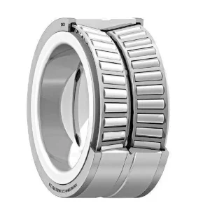
Double-Row Configurations: Enhancing Rigidity and Load Capacity
A double-row tapered roller bearing is essentially two single-row bearings combined into a single, non-separable unit. This offers several practical advantages. The two rows of rollers are typically arranged in a back-to-back configuration, providing high rigidity and moment load capacity in a compact package.
There are two main types of double-row bearings:
- TDO (Two-Row Double Outer): This design features a single double-cup (outer ring) and two single cones (inner rings). The double-cup has two raceways, and the two cone assemblies are mounted on it. There is often a spacer between the two cones to set the internal clearance or preload at the factory. This simplifies assembly, as the user does not need to set the preload themselves.
- TDI (Two-Row Double Inner): This design features a single double-cone (inner ring) with two raceways and two separate cups (outer rings). This configuration is often used in applications where the bearing needs to be mounted on a rotating shaft and the cups are fitted into a stationary housing. Like the TDO, the internal clearance is typically preset with a cone spacer.
Double-row bearings are workhorses in heavy industry. You will find them in the gear drives of large conveyors, the wheels of mining trucks, and the sheaves of massive cranes. Their pre-set clearance eliminates the risk of incorrect preload setting during installation, making them a more robust solution in field service situations. They can handle heavy radial loads, axial loads in both directions, and significant moment loads, all within a single bearing envelope.
Four-Row Assemblies: The Go-To for Heavy-Duty Rolling Mills
When the loads become truly colossal, even a double-row bearing is not enough. This is the domain of the four-row tapered roller bearing. These are complex, high-precision assemblies designed almost exclusively for one application: the roll necks of rolling mills in the steel and aluminum industries.
In a rolling mill, massive steel or aluminum slabs are passed between enormous rollers under immense pressure to reduce their thickness. The bearings supporting these rolls must withstand staggering radial loads while operating in a hot, wet, and dirty environment.
A four-row tapered roller bearing is designed to handle these pure radial loads. It consists of two double-cone assemblies and two single cups, or sometimes a double-cup, mounted with spacers to properly distribute the load across all four rows of rollers. They have very little axial load capacity; separate thrust bearings are used to position the roll axially.
The manufacturing of these bearings is a feat of engineering. The components must be made with exceptional precision to ensure the load is shared equally among the hundreds of rollers in the assembly. Any small geometric error would cause one row to be overloaded, leading to a catastrophic failure that could shut down an entire production line. For those interested in such specialized components, one can typically explore a wide range of tapered roller bearings from specialized suppliers to find the right fit for such demanding environments.
Insight 4: The Art of Selection – Matching the Bearing to the Application
Selecting the correct tapered roller bearing for a given application is a methodical process that balances performance, life, and cost. It is a dialogue between the demands of the machine and the capabilities of the bearing. A miscalculation here can lead to anything from annoying vibrations to catastrophic equipment failure and costly downtime. The process involves a careful analysis of loads, speeds, operating environment, and desired service life.
Engineers rely on a set of standardized calculations and considerations to guide their choice. It is less about finding a bearing that “fits” and more about finding a bearing that will thrive under a specific set of operational challenges.
Calculating Load Ratings: Static and Dynamic Load Capacities
Every bearing catalog lists two fundamental load ratings for each part number: the basic static load rating (C₀) and the basic dynamic load rating (C).
Static Load Rating (C₀): This rating represents the maximum load a bearing can withstand without permanent damage to the rollers or raceways when it is stationary. The damage, known as brinelling, is a permanent indentation caused by the stress exceeding the material’s elastic limit. The C₀ rating is based on a calculated contact stress of 4000 MPa (megapascals) at the center of the most heavily loaded roller/raceway contact.
You would use the static load rating to check for two conditions:
- When the bearing is subjected to very heavy loads while stationary or rotating very slowly.
- When the bearing experiences short-duration shock loads that are much higher than the normal operating load.
A safety factor is always applied. For example, for smooth, vibration-free operation, the static load might need to be less than 0.5 * C₀. For applications with heavy shock loads, a much higher safety factor is required.
Dynamic Load Rating (C): This is the more commonly used rating and is central to calculating bearing life. The dynamic load rating is a theoretical value representing the constant load under which a population of identical bearings will achieve a basic rating life of one million revolutions with 90% reliability. This is often called the L₁₀ life.
The core of bearing life calculation is the L₁₀ life formula:
L₁₀ = (C / P)ᵖ
Where:
- L₁₀ is the rating life in millions of revolutions.
- C is the basic dynamic load rating.
- P is the equivalent dynamic bearing load.
- p is the life exponent. For roller bearings, including tapered roller bearings, p = 10/3.
The equivalent dynamic load (P) is a calculated value that combines all the actual radial (Fr) and axial (Fa) loads acting on the bearing into a single, theoretical radial load that would have the same effect on bearing life. The formula is:
P = X * Fr + Y * Fa
The factors X (radial factor) and Y (axial factor) are found in the bearing manufacturer’s catalog. Their values depend on the bearing’s geometry (its contact angle) and the ratio of axial to radial load. This calculation is the heart of the selection process. It allows an engineer to take the complex, multi-directional forces within a machine and translate them into a single number that can be used to predict the life of a bearing.
Environmental Factors: Temperature, Contamination, and Speed
The L₁₀ calculation provides a baseline, but the real-world service life of a bearing is profoundly affected by its operating environment. Leading manufacturers, such as those found among leading bearing manufacturers, provide adjustment factors to create a more realistic “adjusted rating life.”
Temperature: Bearings generate heat from friction, and they also absorb heat from their surroundings. Most bearing steels are dimensionally stable up to about 125°C (257°F). Above this temperature, the steel’s hardness and strength begin to decrease, which significantly reduces the bearing’s load-carrying capacity and life. For high-temperature applications, special heat stabilization treatments must be applied to the bearing during manufacturing, or bearings made from special high-temperature steels must be used. High temperatures also degrade lubricants, leading to a loss of the protective oil film.
Contamination: Contamination is the number one enemy of rolling bearings. Hard particles—like dirt, sand, or metal debris—that find their way into the bearing act like grinding paste. They dent the raceways and rollers, creating stress concentrations that become the starting points for fatigue spalling (the flaking away of surface material). Water is another destructive contaminant. It promotes corrosion and can also lead to hydrogen embrittlement of the steel, causing it to crack.
Effective sealing is therefore not an accessory but an integral part of the bearing system. In dirty environments like agriculture or construction, multi-lip seals, labyrinth seals, and protective shields are used to keep contaminants out and lubricant in.
Speed: Every bearing has a limiting speed, which is determined by factors like the cage’s strength, lubricant type, and the ability to dissipate heat. Exceeding this speed can lead to a rapid temperature rise, cage failure, and catastrophic seizure of the bearing. Catalogs list two speed ratings: the reference speed, which is a thermal guideline for open bearings, and the limiting speed, which is a mechanical limit that should not be exceeded.
Application-Specific Choices: Automotive Hubs, Gearboxes, and Mining Equipment
The final selection brings all these factors together in the context of a specific machine.
- Automotive Wheel Hubs: This is a classic application for tapered roller bearings. The system needs to be compact, rigid, and able to handle the vehicle’s weight plus cornering forces. Here, two single-row bearings are often set back-to-back, or more commonly today, a pre-set, sealed, double-row unit called a hub bearing unit is used. These units are designed for easy assembly and a long, maintenance-free life.
- Industrial Gearboxes: Gearboxes contain various gear types (helical, bevel, worm) that generate both radial and axial forces on their supporting shafts. Tapered roller bearings are ideal for supporting these shafts, especially pinion shafts where the bevel gear creates a large thrust load. The high rigidity of the bearings is also beneficial for maintaining precise gear mesh, which reduces noise and improves gear life.
- Mining Equipment: In applications like the pivot points on a large excavator or the gearbox of a rock crusher, the conditions are brutal. Loads are extremely high, shock loads are frequent, and the environment is filled with abrasive dust and moisture. Here, robust, case-hardened, double-row tapered roller bearings are often the only viable choice. They are combined with heavy-duty sealing systems to provide an acceptable service life in an environment that would destroy a lesser bearing in hours.
The selection process is an exercise in foresight, anticipating the challenges a bearing will face over its lifetime and choosing a component with the right inherent capabilities to meet them.
Insight 5: Installation and Mounting – Precision is Paramount
The finest, most precisely manufactured tapered roller bearing in the world can be ruined in minutes by improper installation. Unlike many “drop-in” components, mounting a tapered roller bearing, especially a single-row pair, is a procedure that demands care, cleanliness, and an understanding of the concept of preload. The goal of the installation process is not just to secure the bearing to the shaft and in the housing, but to establish the ideal internal operating environment that will allow it to achieve its maximum potential life.
Mistakes made during installation are one of the leading causes of premature bearing failure. A seemingly small error, like a contaminated workspace or an incorrectly tightened locknut, can initiate a chain reaction of wear and damage that culminates in an expensive and unexpected shutdown.
The Importance of Correct Preload and Clearance Settings
Let’s revisit the concept of clearance and preload.
- Internal Clearance: This is the total distance one ring can be moved relative to the other without load. In a tapered roller bearing, this translates to axial “play” or “end float.” A small amount of clearance is necessary in some applications to accommodate thermal expansion.
- Preload: This is the opposite of clearance. It is a negative clearance condition where an axial load is intentionally applied to the bearing pair to remove all play.
Why would we want to preload a bearing? A properly preloaded tapered roller bearing system exhibits several desirable characteristics:
- Increased Rigidity: Preload removes the internal clearance, making the entire shaft assembly stiffer and less prone to deflecting under load. This is vital for machine tool spindles, where rigidity directly translates to cutting accuracy, and for automotive pinions, where it maintains quiet and efficient gear mesh.
- Improved Rotational Accuracy: By eliminating play, preload reduces runout (the wobble of the shaft as it rotates), leading to smoother and more precise operation.
- Enhanced Load Distribution: Preload ensures that all the rollers are sharing the load more evenly, which can extend the fatigue life of the bearing.
- Prevention of Roller Skidding: In very high-speed or lightly loaded applications, rollers can sometimes slide instead of roll, causing surface damage called smearing. Preload maintains a constant force on the rollers, ensuring they always roll properly.
However, preload is a double-edged sword. While a correct preload is beneficial, an excessive preload is disastrous. Too much internal force creates immense pressure at the roller/raceway contacts, generating excessive friction and heat. The lubricant film breaks down, and the bearing rapidly overheats, leading to a quick and catastrophic failure. The “feel” for correct preload is a combination of science and art, often involving measuring torque, axial displacement, or simply the rotational drag of the shaft.
Step-by-Step Mounting Procedures: Press Fitting vs. Thermal Fitting
The first rule of bearing installation is cleanliness. Work should be done in a clean, dry area. All components—the shaft, the housing, the bearings themselves—should be spotlessly clean and free of burrs or old lubricant. Bearings should be kept in their original packaging until the moment of installation to protect them from dirt and moisture.
There are two primary methods for mounting the cone (inner ring) onto a shaft and the cup (outer ring) into a housing, depending on the type of fit required.
Press Fitting (Cold Mounting): This method is used for smaller bearings where the interference fit (the amount the shaft is larger than the bearing bore) is not too great.
- Inspect: Check the shaft and housing for correct size, roundness, and surface finish.
- Apply Force Correctly: Use a press or a bearing fitting tool (a sleeve and hammer). Crucially, the force must only be applied to the ring being fitted. When pressing a cone onto a shaft, apply force only to the face of the cone. Never transmit the mounting force through the rollers. Doing so will create microscopic dents (brinelling) in the raceways, dooming the bearing from the start.
- Ensure Squareness: The bearing must be driven on perfectly straight. If it cocks on the shaft, it can damage both the bearing bore and the shaft seat.
Thermal Fitting (Hot Mounting): For larger bearings or those with a significant interference fit, the force required for press fitting would be immense and would likely damage the components. The solution is to use temperature to your advantage.
- Heating the Bearing: The bearing cone is heated to expand it. The most common and safest method is to use a thermostatically controlled induction heater. This heats the bearing quickly and evenly without risk of contamination or localized overheating. Never use an open flame like a torch, as this will destroy the bearing’s heat treatment and metallurgy. A typical mounting temperature is around 110°C (230°F).
- Positioning: Once heated, the bearing is quickly placed onto the cool shaft. It will slide on easily.
- Cooling: As the bearing cools, it shrinks, creating a powerful interference fit on the shaft. It must be held firmly against the shaft shoulder as it cools to ensure it is seated correctly. The same principle can be applied in reverse by cooling a shaft with liquid nitrogen to shrink it before inserting it into a bearing or housing, though this is less common.
Common Installation Errors and How to Avoid Them
A post-mortem analysis of failed bearings often reveals that the root cause was an error during installation. Some of the most frequent culprits include:
- Contamination: Dirt, dust, or moisture introduced during mounting. Solution: Impeccable cleanliness.
- Brinelling: Applying mounting force through the rollers. Solution: Always use a proper fitting tool and press only on the ring being fitted.
- Misalignment: The shaft and housing bores are not concentric, or the bearing is cocked on its seat. Solution: Precision machining of components and careful, square mounting.
- Incorrect Preload: Too much or too little axial load on the bearing pair. Solution: Follow the manufacturer’s procedure precisely, using torque wrenches, dial indicators, or specialized setting tools.
- Physical Damage: Dropping the bearing or hitting it directly with a hammer. Solution: Handle bearings with care; they are precision instruments.
- Shaft/Housing Fit Errors: The shaft is too large/small, or the housing bore is out of round. Solution: Measure all components with calipers or micrometers before assembly to verify they are within the specified tolerances.
Proper installation is an investment. The extra time taken to ensure cleanliness, use the right tools, and follow the correct procedure pays for itself many times over in the form of reliable machine operation and extended service life.
Insight 6: Lubrication and Maintenance – The Lifeline of a Bearing
If the bearing’s material is its heart, then lubrication is its circulatory system. A thin film of oil or grease, often no thicker than a fraction of a human hair, is the only thing that separates the rolling elements from the raceways under immense pressure. Without this film, the metal-on-metal contact would cause a temperature spike and catastrophic welding and seizure in seconds. Effective lubrication is the single most influential factor in achieving a bearing’s potential service life.
A well-formulated lubrication and maintenance strategy does more than just reduce friction. It also helps to dissipate heat, protect against corrosion, and flush away contaminants that may have entered the bearing. Neglecting lubrication is like expecting an engine to run without oil—the outcome is predictable and disastrous.
Grease vs. Oil Lubrication: Making the Right Choice
The first decision in any lubrication strategy is whether to use grease or oil. Over 80% of rolling bearings are grease-lubricated due to its simplicity and convenience.
Grease Lubrication: Grease is essentially a sponge that holds oil. It consists of a base oil (the lubricant), a thickener (the sponge), and additives.
- Advantages: Grease is simple to apply, stays in place, and provides a good sealing effect against contaminants. It is ideal for sealed-for-life bearing units and applications where frequent relubrication is impractical.
- Disadvantages: Grease has limited ability to dissipate heat. At very high speeds, the churning of the grease can generate significant heat itself.
- Selection: Choosing a grease involves matching the base oil viscosity to the bearing’s speed and load, the thickener type (e.g., lithium complex, polyurea) to the operating temperature and conditions, and the consistency (NLGI grade) to the application’s needs.
Oil Lubrication: Oil is used when speeds or temperatures are high, or when heat needs to be actively removed from the bearing.
- Advantages: Oil is an excellent coolant. In a circulating oil system, it can be filtered and cooled, providing a continuous supply of clean, optimal-viscosity lubricant to the bearing. This is the preferred method for high-speed machine tool spindles and hot-running industrial gearboxes.
- Disadvantages: Oil systems (pumps, reservoirs, filters, plumbing) are more complex and expensive to design and maintain than grease lubrication. Sealing is also more challenging.
- Methods: Oil can be applied via a simple oil bath, a drip feed, or a sophisticated circulating system. The choice depends on the amount of heat that needs to be removed.
The fundamental goal for both oil and grease is to create an elastohydrodynamic lubrication (EHL) film. Under the intense pressure at the roller/raceway contact, the lubricant’s viscosity increases dramatically, and the steel surfaces elastically deform slightly. This creates a stiff, protective film that prevents any direct metal-to-metal contact. The health of this film is paramount.
Establishing a Proactive Maintenance Schedule
Maintenance for tapered roller bearings is not about fixing them when they break; it is about creating the conditions for them to never fail unexpectedly. A proactive approach focuses on maintaining the health of the lubricant and monitoring the condition of the bearing.
A key task is relubrication. Lubricants degrade over time due to high temperatures and oxidation. The oil bleeds out of grease, and additives get depleted. The manufacturer’s guidelines provide a starting point for determining relubrication intervals, but these must be adjusted for real-world conditions. A bearing operating in a hot, wet, or dirty environment will need to be relubricated much more frequently than one in a clean, temperature-controlled room.
The procedure for relubrication is just as important as the interval. When relubricating with grease, it is vital not to overfill the bearing housing. A common rule of thumb is to fill the bearing itself completely and the free space in the housing to about one-third or one-half. Over-greasing can cause the bearing to overheat due to churning, leading to rapid failure. The old, degraded grease should be purged if possible.
Condition Monitoring is the practice of regularly checking the health of an operating bearing. This can range from simple sensory checks (listening for unusual noises, feeling for excess heat) to sophisticated technological methods:
- Vibration Analysis: This is the most powerful technique. As a bearing begins to develop microscopic defects, it emits unique vibration frequencies. A trained analyst with a data collector can detect these tiny signals months before the bearing is in any danger of failing, allowing for a planned replacement during a scheduled shutdown.
- Thermography: Using an infrared camera to monitor bearing temperatures can reveal problems with lubrication or excessive preload.
- Oil Analysis: For oil-lubricated systems, taking regular samples of the oil and sending them to a lab can reveal a wealth of information about the condition of both the lubricant and the machine. The presence of wear metals can pinpoint which component is deteriorating.
Diagnosing Bearing Failure: A Guide to Visual Inspection and Analysis
When a bearing does fail, it is a valuable learning opportunity. A careful visual inspection of the failed components can often reveal the root cause of the failure, allowing for corrective actions to be taken to prevent a recurrence. The patterns of damage on the raceways and rollers are like fingerprints that tell a story.
Some common failure modes include:
- Fatigue (Spalling): This is the “natural” end of a bearing’s life. It appears as a flaking or pitting of the raceway surface, caused by the millions of stress cycles the material has endured. If it occurs prematurely, it points to overloading or an incorrect bearing selection.
- Wear: Abrasive wear appears as dull, lapped surfaces caused by fine contaminants. Adhesive wear (smearing) is caused by rollers sliding instead of rolling under poor lubrication.
- Corrosion: Red/brown rust or black etching on the surfaces, caused by exposure to water or corrosive agents. Fretting corrosion appears as rust-colored stains at the contact points between the bearing bore and shaft, caused by micro-movement due to a loose fit.
- Electrical Damage (Fluting): In applications with electric motors, stray electrical currents can pass through the bearing, creating sparks that melt and pit the surface. This results in a distinctive washboard-like pattern called fluting.
- Brinelling and False Brinelling: True brinelling is indentation from impact or static overload. False brinelling occurs in stationary equipment subject to vibration, where the lubricant is pushed away and the micro-movements cause wear in the shape of the rollers.
- Fracture: A cracked ring or roller is a catastrophic failure, often resulting from extreme stress caused by excessive preload, a very heavy shock load, or improper mounting (e.g., hitting the bearing with a hammer).
Understanding these failure modes allows maintenance professionals to become detectives, diagnosing the underlying problem instead of just repeatedly replacing the failed component.
Insight 7: The Future of Bearing Technology – Trends and Innovations for 2025 and Beyond
The world of tapered roller bearings is not static. While the fundamental principles have remained unchanged for over a century, the technology is continuously evolving. Driven by the demands for greater efficiency, higher reliability, and the integration of machinery into the Internet of Things (IoT), bearing technology in 2025 is smarter, more durable, and more sustainable than ever before. These innovations are transforming bearings from simple mechanical components into active, data-providing elements of a larger digital ecosystem.
The future is focused on making bearings that not only last longer but also communicate their health, enabling a truly predictive and proactive approach to industrial maintenance. A visit to a site that outlines a history of innovation can show how far the industry has come.
Smart Bearings and Integrated Sensor Units
The most significant trend is the fusion of mechanical bearings with digital technology. A “smart bearing” is no longer just a passive component; it is an active node in a data network.
Integrated Sensors: Manufacturers are now embedding miniature sensors directly into bearing units. These sensors can measure critical parameters in real-time, right at the heart of the action:
- Vibration: An integrated accelerometer can provide clean, high-fidelity vibration data, far more accurate than data from an externally mounted sensor.
- Temperature: A sensor on the bearing ring provides the most accurate measurement of operating temperature.
- Load: Some advanced units can measure the actual loads the bearing is experiencing.
- Speed: A rotational speed sensor can track the exact RPM of the shaft.
This data can be transmitted wirelessly to a local gateway or directly to the cloud. This allows for continuous, 24/7 condition monitoring without the need for a technician to walk around with a handheld device. The system can automatically flag anomalies, alert maintenance staff to developing problems, and provide a rich dataset for performance optimization. For industries like wind energy, where a bearing failure in a nacelle hundreds of feet in the air is incredibly costly, this technology is a game-changer.
Advanced Materials and Sustainable Manufacturing
The quest for better materials is relentless. While steel remains the primary material, research is pushing into new frontiers.
Ceramic Hybrids: Hybrid bearings, which use steel rings and ceramic (typically silicon nitride) rollers, offer remarkable properties. Ceramic rollers are 60% less dense than steel, harder, and have a lower coefficient of thermal expansion. This makes them ideal for very high-speed applications. They are also excellent electrical insulators, which completely eliminates the problem of electrical damage in electric motor applications. While currently more common in ball bearings, the use of ceramics in specialized roller bearings is growing.
Advanced Coatings: Beyond DLC, researchers are developing new multi-layer and nanocomposite coatings that can self-heal or adapt to changing operating conditions. These “chameleon” coatings could offer ultra-low friction across a wide range of temperatures and lubrication regimes.
Sustainability: The bearing industry is also focusing on sustainability. This includes:
- Remanufacturing: Large, expensive industrial bearings, like those used in rolling mills or wind turbines, can often be remanufactured. The bearing is returned to the factory, disassembled, cleaned, inspected, and any worn components are replaced or re-ground. A remanufactured bearing can offer the same performance and life as a new one but at a lower cost and with a significantly smaller carbon footprint.
- Energy Efficiency: Every bit of friction in a bearing is wasted energy. New generations of low-friction tapered roller bearings are being designed with optimized internal geometry and surface finishes to reduce frictional losses, contributing to the overall energy efficiency of the machine.
The Growing Importance of Simulation and Digital Twins
In the past, bearing selection and application design relied on catalog formulas and empirical rules. Today, powerful software tools allow engineers to simulate the performance of a bearing system with incredible accuracy.
Advanced Simulation Software: Engineers can build a virtual model of a complete gearbox or machine, including shafts, gears, and bearings. They can then apply realistic load cycles and environmental conditions and see how the system behaves. The software can calculate detailed stress distributions within the bearings, predict lubricant film thickness, and estimate fatigue life with a high degree of confidence. This allows for optimization of the design before any metal is cut, reducing the need for costly physical prototyping and testing.
Digital Twins: The concept of the digital twin takes this a step further. A digital twin is a virtual replica of a specific physical asset—not just a generic model, but a digital copy of your specific machine. This twin is fed real-time data from the smart sensors on the actual machine.
By combining the physics-based simulation model with live operational data, the digital twin can:
- Accurately track the “health” and remaining useful life of the bearing.
- Simulate the effect of changing operating parameters (e.g., “What happens if we increase the load by 10%?”).
- Run “what-if” scenarios for maintenance, helping to optimize schedules and spare parts inventory.
This technology represents a move from preventive maintenance (fixing things on a schedule) and predictive maintenance (fixing things when data suggests a problem) to prescriptive maintenance, where the system itself can recommend actions to extend life and improve performance.
The tapered roller bearing, a component born in the age of steam and steel, is proving itself to be an essential part of the digital industrial revolution of the 21st century.
Frequently Asked Questions (FAQ)
What is the main advantage of a tapered roller bearing over a ball bearing? The primary advantage is their ability to handle heavy combined loads. Their conical design allows them to support significant radial (perpendicular to the shaft) and axial (parallel to the shaft) forces simultaneously. A standard ball bearing is less effective under heavy axial loads, making tapered roller bearings superior for applications like vehicle wheels and gearbox pinions.
Why do single-row tapered roller bearings need to be installed in pairs? When a single-row bearing is subjected to a radial load, its angled design creates an induced axial force. A single bearing cannot counteract this force on its own. By mounting two bearings in opposition (either “back-to-back” or “face-to-face”), the induced axial force from one bearing is supported by the other, creating a stable and rigid system.
What is preload and why is it important? Preload is a deliberate internal axial force applied to a bearing pair during installation to eliminate all clearance. Correct preload is vital because it increases the system’s rigidity, improves rotational accuracy, and ensures even load distribution across the rollers, which can extend bearing life. However, excessive preload causes overheating and rapid failure.
How do I know if I should use grease or oil for my bearing? Use grease for most applications, especially where speeds are moderate, temperatures are not extreme, and simplicity is desired. Grease is easy to contain and helps seal out contaminants. Use oil for high-speed or high-temperature applications where heat removal is necessary. Circulating oil systems provide the best cooling and lubrication but are more complex.
What is the most common cause of premature bearing failure? Contamination is widely cited as the leading cause of premature failure. Hard particles (dirt, sand) or moisture entering the bearing can damage the finely finished surfaces, leading to wear and fatigue. This is followed closely by issues related to improper lubrication (too little, too much, or the wrong type) and incorrect installation practices.
Can a tapered roller bearing be mounted in any orientation? Yes, tapered roller bearings can be mounted in any orientation—horizontally, vertically, or at an angle—as long as they are properly lubricated and supported. The internal geometry is designed to function irrespective of the mounting position.
What does the L₁₀ life of a bearing mean? The L₁₀ life is the basic rating life. It represents the number of revolutions that 90% of a population of identical bearings are expected to complete or exceed before the first signs of fatigue appear. It is a statistical measure of reliability used for calculating and comparing bearing life.
How can I tell if a bearing is starting to fail? Early warning signs include an increase in vibration, a change in operating sound (e.g., from a smooth hum to a rumbling or whining noise), or a rise in operating temperature. Using condition monitoring tools like vibration analysis or thermography is the most reliable way to detect failure in its earliest stages.
Conclusion
The tapered roller bearing stands as a testament to the power of thoughtful geometric design. Its ability to manage complex, combined loads with high rigidity has made it an irreplaceable component in the machinery that underpins our modern world. From the cars we drive to the steel we build with and the energy we generate, these bearings are the silent enablers of motion and strength. Understanding their function is not merely an academic exercise; it is a practical necessity for anyone involved in the design, operation, or maintenance of industrial equipment.
A successful application hinges on a holistic appreciation of the bearing’s lifecycle—from the metallurgical science that forges its strength, through the meticulous process of selection and precision installation, to the vigilant practices of lubrication and condition monitoring. As technology progresses into 2025 and beyond, the integration of sensors and digital simulation will continue to elevate the capabilities of these remarkable components, transforming them into intelligent participants in an interconnected industrial ecosystem. The principles of load, life, and lubrication remain the cornerstones of reliability, ensuring that the tapered roller bearing will continue its vital work for many years to come.