Abstract
A ball bearing is a fundamental mechanical component designed to reduce rotational friction and support radial and axial loads between machine parts. It achieves this by utilizing spherical rolling elements situated between two concentric rings, known as races. The primary function involves constraining relative motion to only the desired rotation, thereby enhancing efficiency and reducing wear. These components consist of an inner race, an outer race, a set of balls, and a cage that maintains the separation between the balls. The evolution of the ball bearing from rudimentary concepts to high-precision engineered devices has been pivotal for advancements across countless industries, including automotive, aerospace, agriculture, and manufacturing. The selection of an appropriate bearing is a complex decision contingent upon a nuanced understanding of application-specific parameters such as load magnitude and direction, rotational speed, required precision, and operating environment. Proper specification and maintenance are paramount for achieving optimal machine performance, reliability, and service life.
Key Takeaways
- Loads are a primary factor; identify if they are radial, axial, or combined.
- Match the bearing's speed rating to your application's rotational demands.
- Consider environmental factors like contamination, temperature, and moisture.
- Select the correct type, as a deep groove ball bearing serves a different purpose than a thrust bearing.
- Proper lubrication and mounting are as vital as the bearing itself.
- Evaluate the required precision level (ABEC/ISO rating) for your machinery.
Table of Contents
- The Fundamental Principles of the Ball Bearing: A World in Motion
- Factor 1: Understanding Load and Its Influence on Bearing Selection
- Factor 2: Speed and Rotational Demands: The Pursuit of High Performance
- Factor 3: Precision, Rigidity, and Environmental Conditions
- Factor 4: A Deep Dive into the Four Major Types of Ball Bearings
- Factor 5: The Ecosystem of Support: Lubrication, Mounting, and Maintenance
- Frequently Asked Questions (FAQ)
- Conclusion
- References
The Fundamental Principles of the Ball Bearing: A World in Motion
To begin our exploration, let us first establish a foundational understanding. Imagine trying to spin a heavy wagon wheel on a simple, fixed axle. The metal of the wheel hub grinds directly against the metal of the axle. The resulting friction creates heat, wears down the components, and demands a great deal of energy to initiate and sustain motion. Now, imagine placing a series of small, smooth spheres between the wheel hub and the axle. Suddenly, the grinding, sliding motion is replaced by a fluid, rolling motion. The effort required to spin the wheel plummets. You have just grasped the essential principle of a ball bearing. It is a device that substitutes the high friction of sliding contact with the significantly lower friction of rolling contact (Tata, 2011).
This elegant solution is not merely a component; it represents a conceptual leap in mechanical engineering, enabling the high-speed, high-efficiency world we inhabit. From the tiny motors in a dental drill to the massive turbines generating power for our cities, the ball bearing is an unsung hero, silently facilitating motion. Its purpose is to support and guide rotating or oscillating machine elements, such as shafts or axles, and to transfer forces between different parts of a machine with minimal energy loss .
Deconstructing the Bearing: What Lies Within?
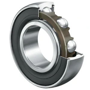
At its heart, a standard ball bearing is an assembly of four primary parts, each with a distinct and indispensable role. Thinking of it as a miniature planetary system can be a helpful mental model.
- The Outer Race: This is the stationary sun at the center of our system, though in reality, it is the outermost ring. It typically fits snugly into a housing or machine frame. Its inner surface is a precisely ground track, or raceway, upon which the balls roll.
- The Inner Race: This is the planet, the rotating element. It fits tightly onto the rotating shaft or axle. Its outer surface features another perfectly matched raceway for the balls. The relative motion between the inner and outer race is what the bearing facilitates.
- The Rolling Elements (Balls): These are the moons, orbiting between the sun and the planet. They are highly spherical, incredibly hard, and smooth balls that roll within the raceways. They are the elements that carry the load and transform sliding friction into rolling friction. The number and size of the balls are key determinants of the bearing's load-carrying capacity.
- The Cage (or Retainer): This is the invisible force of gravity that keeps our planetary system orderly. The cage is a separator that fits between the balls, maintaining their even spacing around the raceways. Without a cage, the balls would bunch up, rub against each other, generate immense friction and noise, and lead to rapid failure. The cage ensures smooth, quiet operation and even load distribution.
These four components work in concert, a testament to precision manufacturing. The minute space between the balls and the races, known as internal clearance, is a carefully engineered parameter that allows for thermal expansion and proper lubrication, which we will explore in greater detail later.
The Physics of Friction Reduction: From Sliding to Rolling
The genius of the ball bearing lies in its exploitation of a fundamental physical principle: rolling friction is substantially lower than sliding friction. When two surfaces slide against each other, microscopic imperfections on each surface, called asperities, catch and snag. To overcome this, one must constantly break and deform these microscopic welds, which manifests as a high frictional force and generates significant heat.
A ball bearing changes the nature of this interaction. Instead of large surfaces sliding past one another, the load is concentrated at very small contact points between the balls and the raceways. As the bearing rotates, the balls roll with minimal deformation of the material at these contact points. The energy required to continuously deform these tiny areas is far less than the energy needed to shear the asperities in sliding contact. The result is a dramatic reduction in friction, often by a factor of 100 or more. This efficiency gain translates directly into less energy consumption, lower heat generation, reduced wear on components, and the ability to achieve much higher rotational speeds (Tata, 2011).
A Historical Perspective: From Ancient Rollers to Modern Precision
The concept of reducing friction through rolling is not a modern invention. There is evidence that ancient civilizations, such as the Egyptians, used logs as rollers to move massive stone blocks for constructing pyramids and monuments. They understood, on a practical level, that rolling a heavy object was easier than dragging it.
The first documented design for a bearing that resembles our modern understanding comes from the notebooks of Leonardo da Vinci around the year 1500. His sketches show concepts for separating rolling elements to reduce friction, a precursor to the modern bearing cage. However, the materials and manufacturing technologies of his time were insufficient to bring these ideas to fruition.
The true birth of the modern ball bearing occurred during the Industrial Revolution. With the advent of steam engines and machinery that operated at previously unimaginable speeds, the problem of friction became a major engineering bottleneck. The first patent for a radial-style ball bearing was awarded to Philip Vaughan, a Welsh ironmaster, in 1794 for an axle assembly. The 19th century saw rapid development, with innovations in grinding techniques and steel manufacturing allowing for the creation of harder, more precise balls and races. By the late 1800s, companies like FAG and SKF were founded, beginning the mass production of standardized bearings that would fuel the second industrial revolution and the rise of the automobile, the airplane, and countless other technologies (Schaeffler KG, 2009).
Factor 1: Understanding Load and Its Influence on Bearing Selection
The first and most foundational consideration in selecting a ball bearing is the nature of the load it will be expected to endure. The term 'load' refers to the forces acting upon the bearing. Misunderstanding or miscalculating these forces is perhaps the most common reason for premature bearing failure. The forces are not just about magnitude (how heavy the load is) but also about direction. Imagine holding a heavy bucket. Holding it straight down with your arm is one type of load. Trying to hold it out to your side is another entirely. Bearings experience forces in a similar way, and they are broadly categorized into radial loads, axial loads, and combined loads.
Radial Loads: The Force from the Side
A radial load is a force that acts perpendicularly to the axis of the shaft, or, put more simply, it pushes on the side of the bearing. Think of the wheels on a bicycle. As you ride, your weight pushes down through the frame and onto the axles of the wheels. This downward force on the axle is a classic example of a radial load. The bearing in the wheel hub must support this force that is radiating outwards from the center of the axle.
Most types of ball bearings can handle some degree of radial load. However, the deep groove ball bearing is the quintessential champion of radial loads. Its design features a deep, symmetrical groove in both the inner and outer races, which cradles the balls perfectly. This design allows it to support substantial radial forces while also permitting high-speed operation. Applications like electric motors, conveyor belt rollers, and gearboxes predominantly feature radial loads, making deep groove ball bearings a common choice.
Axial (Thrust) Loads: The Force Along the Shaft
An axial load, also known as a thrust load, is a force that acts parallel to the axis of the shaft. It pushes or pulls along the length of the shaft. A simple, relatable example is a rotating bar stool. When someone sits on the stool and spins, their entire weight is an axial load pushing down on the bearing mechanism that allows it to turn. Another example would be the propeller on a boat; as it spins, it generates a thrust force that pushes the boat forward, and this force is transmitted along the propeller shaft as an axial load.
Not all ball bearings are equipped to handle axial loads. A standard deep groove ball bearing can manage light to moderate axial loads, but if the thrust force is the primary or dominant load, a specialized bearing is required. This is the domain of the thrust ball bearing. Its design is different; instead of inner and outer rings, it consists of two washer-like plates with grooved raceways, with the balls sandwiched between them. This configuration is specifically designed to support forces pushing along the shaft's axis but typically cannot handle any significant radial load.
Combined Loads: The Reality of Complex Applications
In the real world of mechanical design, forces are rarely as simple as being purely radial or purely axial. Most applications subject bearings to a combination of both. Consider the front wheel of a car. The weight of the car creates a radial load. When the car turns a corner, cornering forces create a strong axial load on the wheel bearings. The bearing must handle both simultaneously. This is known as a combined load.
For applications with combined loads, the angular contact ball bearing is the superior choice. Its name gives a clue to its design. The raceways in the inner and outer rings are offset relative to each other. This geometry means that the load is transmitted from one raceway to the other at a specific contact angle. This angle allows the bearing to effectively support both a significant radial load and a substantial axial load in one direction. For handling axial loads in both directions, angular contact bearings are often mounted in pairs, in either a "back-to-back" or "face-to-face" arrangement. This paired configuration is standard in high-precision applications like machine tool spindles and automotive wheel hubs.
Static versus Dynamic Loads: A Critical Distinction
Finally, we must distinguish between static and dynamic loads. A dynamic load is the load that a bearing is subjected to while it is rotating. The bearing's ability to withstand this is defined by its Basic Dynamic Load Rating (C). This rating is a theoretical value used to calculate the bearing's expected fatigue life under a given set of conditions.
A static load, conversely, is the load on a bearing when it is stationary, or when rotation is very slow or infrequent. It also includes shock loads or heavy temporary overloads that might occur even when the bearing is rotating. The bearing's capacity to handle such loads without permanent damage is given by its Basic Static Load Rating (C0). This rating relates to the permanent deformation (called brinelling) that occurs in the raceways when a stationary bearing is overloaded. If the static load exceeds C0, tiny dents will be formed in the raceways by the balls, leading to noise, vibration, and a drastically shortened life once rotation begins. Therefore, one must consider not only the normal operating loads but also any potential shock loads when selecting a bearing.
| Bearing Type | Radial Load Capacity | Axial Load Capacity | Misalignment Tolerance | Primary Applications |
|---|---|---|---|---|
| Deep Groove Ball Bearing | Excellent | Moderate (in both directions) | Low | Electric Motors, Gearboxes, Pumps, Fans |
| Angular Contact Ball Bearing | Good | Excellent (in one direction) | Very Low | Machine Tool Spindles, Wheel Hubs |
| Self-Aligning Ball Bearing | Good | Low | Excellent | Agricultural Machinery, Conveyors |
| Thrust Ball Bearing | Very Poor / None | Excellent (in one or both directions) | None | Turntables, Crane Hooks, Jack Screws |
Factor 2: Speed and Rotational Demands: The Pursuit of High Performance
After analyzing the loads, the next critical factor to evaluate is speed. The rotational speed of an application profoundly impacts the performance, temperature, and lifespan of a ball bearing. A bearing that performs flawlessly in a low-speed conveyor system would fail catastrophically in a high-speed machine tool spindle. Understanding the relationship between speed, heat, and bearing design is paramount for ensuring reliability. Every bearing has a speed limit, and exceeding it is a direct path to failure.
The Concept of Limiting Speed
Every bearing catalog lists two important speed ratings: the reference speed and the limiting speed.
The reference speed is a standardized thermal speed rating based on a specific set of operating conditions (load, lubrication, cooling). It provides a useful benchmark for comparing the speed capabilities of different bearings under a common framework.
The limiting speed, on the other hand, is a more practical mechanical limit. It is the maximum rotational speed at which a bearing can operate continuously without risk of seizure or rapid mechanical failure. This limit is determined by several factors, including the strength and stability of the cage, the precision of the bearing's geometry, the centrifugal forces acting on the rolling elements, and the type of lubrication used. As the bearing spins faster, the balls are forced outwards by centrifugal force, which increases the pressure and friction at the outer race contact point. The cage must also withstand these increasing forces to keep the balls properly separated. At the limiting speed, these mechanical stresses approach the design limits of the bearing's components.
Heat Generation at High Speeds: The Unseen Enemy
As a ball bearing rotates, it inevitably generates heat. This heat comes from three main sources: the elastic deformation of the balls and raceways under load, the sliding friction between the balls and the cage, and the viscous drag or "churning" of the lubricant. At low to moderate speeds, this heat is usually minimal and can be dissipated into the shaft and housing without issue.
However, as rotational speed increases, heat generation rises exponentially. If this heat cannot be dissipated effectively, the bearing's temperature will climb. The consequences of excessive temperature are severe:
- Lubricant Degradation: High temperatures cause the lubricant (grease or oil) to break down. The oil can oxidize, thicken, and lose its lubricating properties, while the thickener in grease can separate from the oil. This leads to lubricant starvation and metal-to-metal contact.
- Thermal Expansion: The inner ring, being tightly fitted to the shaft, tends to get hotter than the outer ring. This causes it to expand more, which reduces the bearing's internal clearance. If the clearance is reduced to zero or less, the bearing becomes preloaded, dramatically increasing friction and leading to a thermal runaway spiral where more heat creates more friction, which creates even more heat, until the bearing seizes.
- Reduced Material Hardness: The high-carbon chromium steel used for most bearings will begin to lose its hardness and strength if its temperature exceeds a certain limit (typically around 125-150°C for standard steel). This softening makes the raceways more susceptible to wear and permanent deformation, drastically shortening the bearing's life.
Bearing Design for High-Speed Applications
To combat the challenges of high speed, engineers have developed specialized bearing designs and materials. For applications demanding the utmost speed, such as in aerospace or high-performance racing, standard steel bearings are often inadequate.
One of the most significant innovations is the hybrid ceramic ball bearing. In these bearings, the steel balls are replaced with balls made from a ceramic material, typically silicon nitride (Si3N4). Ceramic balls offer several advantages for high-speed operation:
- Lower Density: They are about 40% less dense than steel balls. This means they generate significantly lower centrifugal forces at high speeds, reducing friction and stress on the outer race.
- Higher Hardness: Ceramic is harder than steel, making it more resistant to wear and surface damage from contaminants.
- Lower Thermal Expansion: They expand much less with temperature changes, making the bearing less sensitive to thermal preloading.
- Non-Conductive: Being an electrical insulator, they prevent damage from electrical current arcing through the bearing, a common problem in electric motor applications.
Beyond materials, manufacturing precision is key. High-speed bearings are manufactured to much tighter tolerances, specified by ABEC (Annular Bearing Engineers' Committee) or ISO (International Organization for Standardization) precision classes. A higher class number (e.g., ABEC 7 or ABEC 9) indicates tighter tolerances on the bearing's dimensions and runout (wobble), which is essential for smooth, stable operation at high RPM. The cage design is also modified. Instead of a standard stamped steel cage, high-speed bearings often use precision-machined brass or lightweight, low-friction polymer cages (like polyamide or phenolic resin) that are better able to withstand the high centrifugal forces and provide better lubrication guidance.
Lubrication's Role in Speed Management
Lubrication is the lifeblood of a bearing, and its role becomes even more pronounced at high speeds. The choice between grease and oil is a fundamental one.
Grease lubrication is the most common method. Grease is essentially a sponge (a thickener, like a metallic soap) that holds lubricating oil. It is simple to apply, provides good protection against contaminants, and requires minimal maintenance, which is why it is used in the vast majority of applications. However, grease has its speed limitations. At high speeds, the churning of the thick grease can generate excessive heat.
Oil lubrication is the preferred method for high-speed applications. Oil is a more effective lubricant at high speeds because it has a lower viscosity and, more importantly, it can be used to actively cool the bearing. There are several methods of oil lubrication:
- Oil Bath: The bearing housing is partially filled with oil, and the rotating components splash through it. Simple, but can cause churning and heat at very high speeds.
- Oil Mist: A fine mist of oil and compressed air is directed through the bearing. This provides minimal lubrication, reducing viscous drag, and the airflow provides some cooling.
- Oil Jet: A high-velocity jet of oil is sprayed directly onto the bearing's internal components. This is the most effective method for extreme-speed applications, as the high flow rate of oil provides both excellent lubrication and aggressive cooling, carrying heat away from the bearing.
The selection of the correct lubricant and delivery method is a complex science, but it is an inseparable part of designing a reliable high-speed rotating system.
| Lubrication Type | Typical Speed Range | Temperature Management | Sealing Capability | Maintenance Requirement |
|---|---|---|---|---|
| Grease | Low to Moderate | Poor (relies on passive dissipation) | Excellent (grease pack helps seal) | Low (often lubricated for life) |
| Oil Bath | Moderate to High | Fair (oil volume provides cooling mass) | Fair (requires external seals) | Moderate (oil level monitoring) |
| Oil Mist / Air-Oil | High to Very High | Good (airflow provides cooling) | Poor (requires external seals) | High (requires complex system) |
| Oil Jet | Very High to Extreme | Excellent (active cooling) | Poor (requires external seals) | High (requires pumps, filters, coolers) |
Factor 3: Precision, Rigidity, and Environmental Conditions
Beyond load and speed, a third set of interconnected factors demands careful consideration: the required precision of the application, the need for system rigidity, and the environment in which the bearing will operate. These elements move us from the theoretical world of forces and velocities into the practical realities of machine performance and longevity. A bearing that is perfectly suited for a cleanroom environment would perish in the dusty fields of a farm, and a bearing that is adequate for a simple fan would be wholly insufficient for a precision CNC machine.
The ABEC/ISO Scale: Quantifying Precision
Not all bearings are created equal. The term 'precision' in the context of bearings refers to the manufacturing tolerances to which the component is made. A more precise bearing will have less 'runout'—that is, less wobble or deviation from a perfect axis of rotation. This precision is standardized and graded according to scales established by the Annular Bearing Engineers' Committee (ABEC) in the United States, or the International Organization for Standardization (ISO 492) globally.
The scales are roughly equivalent, with higher numbers indicating higher precision:
- ABEC 1 / ISO Class Normal: Standard precision, suitable for the vast majority of general-purpose applications like wheels, skateboards, and many industrial motors.
- ABEC 3 / ISO Class 6: A step up in precision, often used in more demanding electric motors and general machine tools.
- ABEC 5 / ISO Class 5: High precision, common in applications requiring smoother, quieter operation and higher speeds, such as routers and some machine tool spindles.
- ABEC 7 / ISO Class 4: Super precision, used where high rotational accuracy is paramount. This is the realm of precision grinding spindles, aerospace instruments, and high-performance machinery.
- ABEC 9 / ISO Class 2: Ultra precision, the highest standard, reserved for laboratory instruments, computer disk drives, and the most demanding high-speed, high-accuracy machine tools.
Why does this matter? Imagine a CNC milling machine cutting a precise part. If the bearing in the spindle has significant runout, the cutting tool will wobble, resulting in a poor surface finish and dimensional inaccuracies on the workpiece. In a high-speed dental drill, a lack of precision would cause excessive vibration, leading to discomfort for the patient and a lack of control for the dentist. Choosing a higher precision bearing reduces rotational error, lowers vibration and noise, and often allows for higher speed capabilities. However, precision comes at a cost, so it is uneconomical to specify an ABEC 7 bearing for an application that would perform perfectly well with an ABEC 1. The key is to match the bearing's precision to the application's genuine requirements.
Bearing Rigidity: Resisting Deformation Under Load
Rigidity, or stiffness, refers to a bearing's ability to resist deflection or deformation when a load is applied. While we often think of steel as being completely solid, under the immense pressures inside a bearing, the balls and raceways do deform elastically by a microscopic amount. The amount of this deformation determines the bearing's rigidity.
High rigidity is desirable in many applications. In a machine tool, a rigid spindle assembly prevents the tool from deflecting away from the workpiece under cutting forces, ensuring accuracy. In a gearbox, high rigidity maintains the precise alignment of the gears, ensuring proper tooth meshing and preventing premature wear.
Several factors influence a bearing's rigidity. Firstly, the type of bearing plays a role. A roller bearing, which makes line contact with the raceway, is inherently more rigid than a ball bearing, which makes point contact. Within ball bearings, an angular contact bearing is generally more rigid than a deep groove ball bearing. Secondly, rigidity can be significantly increased through preloading. Preloading is the practice of applying a permanent axial load to a bearing or a pair of bearings. This internal load removes the initial clearance and forces the balls into constant contact with the raceways. This initial compression means that when an external working load is applied, the amount of additional deflection is much smaller, resulting in a much stiffer system. This is why angular contact bearings in machine tool spindles are almost always installed as preloaded pairs.
Navigating Harsh Environments: Contamination, Temperature, and Corrosion
The operating environment is a silent killer of bearings. A bearing that is perfectly specified for load, speed, and precision can still fail rapidly if it is not protected from its surroundings.
Contamination: Dirt, dust, water, and process fluids are the number one enemy of rolling bearings. A single hard particle, smaller than a grain of sand, that finds its way into the raceway can be crushed between a ball and the race, creating a small dent. Every time a ball rolls over that dent, it creates a noise and a stress concentration, which eventually leads to a fatigue crack and the spalling (flaking) of the raceway surface. To combat this, bearings are often equipped with integral shields or seals.
- Shields (Z or ZZ): These are metal discs fitted into the outer ring that sit very close to the inner ring, creating a narrow gap. They are effective at retaining grease and keeping out larger solid contaminants. Because they are non-contacting, they add no friction and do not limit the bearing's speed.
- Seals (RS or 2RS): These are typically made of a synthetic rubber material (like nitrile) that is bonded to a steel insert. The seal has a "lip" that makes light contact with the inner ring. This contact provides a much more effective barrier against fine dust and moisture. However, the rubbing of the seal lip does create a small amount of friction and heat, which can slightly lower the bearing's maximum speed rating. The choice between a shield and a seal is a trade-off between protection and speed/friction. For a wide selection, you can explore various deep groove ball bearings with different sealing options to find the perfect fit for your environmental conditions.
Temperature: We have already discussed how high speeds generate heat, but the ambient environment can also be a source of extreme temperature. In applications like furnace fans or steel mill rollers, bearings must operate in intense heat. In cryogenic applications, they must function at extremely low temperatures. Standard bearing steel and lubricants are not suitable for these extremes. Special high-temperature steels (like M50), heat stabilization treatments, and special lubricants (like silicone or perfluoropolyether greases) are required. Temperature also affects the bearing's internal clearance and the fits between the bearing, shaft, and housing, all of which must be accounted for in the design.
Corrosion: In food processing plants, marine environments, or chemical processing facilities, bearings are exposed to water, cleaning agents, and corrosive chemicals. Standard steel bearings will rust and corrode quickly in such conditions. For these applications, stainless steel ball bearings are often used. The most common type is 440C stainless steel, which offers good hardness and excellent corrosion resistance. For even more demanding environments, specialized coatings or even bearings made entirely of ceramic or polymer materials may be necessary.
Factor 4: A Deep Dive into the Four Major Types of Ball Bearings
While there are many specialized variations, the world of ball bearings is dominated by four principal families. Each family shares the same fundamental components—races, balls, and a cage—but subtle differences in their internal geometry give them unique performance characteristics. Understanding these four archetypes is akin to a chef understanding the difference between a paring knife, a chef's knife, a bread knife, and a cleaver. Each is a cutting tool, but they are optimized for very different tasks. Choosing the right type of ball bearing is the first step toward a successful and reliable design.
Deep Groove Ball Bearings: The Versatile Workhorse
If there is one type of ball bearing that could be considered the "default" or most common, it is the deep groove ball bearing. Its prevalence is a testament to its balanced design and incredible versatility. Its defining feature, as the name suggests, is the deep, circular groove machined into the inner and outer raceways. The radius of this groove is only slightly larger than the radius of the balls themselves, creating a close conformity.
This geometry is the source of its strengths. The deep groove provides excellent support for radial loads. It also allows the bearing to handle moderate axial loads in both directions, as the balls can ride up the side of the groove when a thrust force is applied. Furthermore, their simple, non-separable design and low-friction characteristics make them suitable for very high rotational speeds. This combination of capabilities, coupled with their relatively low cost and wide availability in countless sizes and configurations (open, shielded, sealed), makes them the workhorse of the bearing world.
You will find deep groove ball bearings in an astonishing array of applications, from the mundane to the critical. They are in the motors of your household appliances like washing machines and vacuum cleaners. They are found throughout automotive systems, in alternators, idler pulleys, and water pumps. They are the backbone of countless industrial machines, including electric motors, pumps, fans, and gearboxes. Their ubiquity makes them a fundamental component of modern mechanical engineering.
Angular Contact Ball Bearings: Mastering Combined Loads
While a deep groove ball bearing can handle some axial load, it is a compromise. When an application involves significant and sustained axial loads acting in concert with radial loads, the angular contact ball bearing is the technically superior solution.
The key design difference is that the raceways are asymmetrical. The shoulder on one side of the groove is higher than the other. This creates a "contact angle" between the balls and the raceways. When you look at a cross-section, the line of force through the balls is not perpendicular to the shaft but is angled. It is this angle that allows the bearing to support a heavy axial load in one direction, along with a radial load.
A single angular contact bearing can only support an axial load in one direction. For this reason, they are almost always used in pairs. By mounting two bearings together, they can handle strong axial forces in both directions. The two most common mounting arrangements are:
- Back-to-Back (DB): The wide faces of the outer rings are adjacent. This configuration provides very high rigidity and is excellent at resisting tilting or moment loads. It's the preferred arrangement for machine tool spindles.
- Face-to-Face (DF): The narrow faces of the outer rings are adjacent. This arrangement is more tolerant of misalignment than the back-to-back setup but is slightly less rigid.
Because of their ability to provide high rigidity and support heavy combined loads at high speeds, angular contact ball bearings are found in demanding, high-precision applications. They are the heart of CNC machine spindles, high-speed pumps and compressors, and high-performance automotive transmissions and differentials.
Self-Aligning Ball Bearings: Forgiving Misalignment
In a perfect world, every shaft would be perfectly straight and rigid, and every bearing housing would be machined and mounted in perfect alignment. In the real world, this is often not the case. Long shafts can bend or deflect under load, and separate bearing housings mounted at a distance can be difficult to align perfectly. Attempting to use a rigid bearing like a deep groove or angular contact type in such a situation would impose huge internal loads on the bearing, leading to rapid failure.
The self-aligning ball bearing is the elegant solution to this problem. It has two rows of balls, but its unique feature is that the outer ring has a single, continuous spherical raceway. The entire inner ring, ball, and cage assembly can pivot freely within this spherical outer raceway. This "ball and socket" design allows the bearing to tolerate several degrees of static or dynamic misalignment between the shaft and the housing without inducing stress.
This ability to self-align makes them indispensable in applications where shaft deflection or mounting inaccuracies are unavoidable. They are commonly found in agricultural machinery, which operates on uneven terrain and has long, flexible shafts. They are also used extensively in conveyor systems, large fans and blowers, and textile machinery. While they are brilliant at handling misalignment, their load-carrying capacity, particularly for axial loads, is more limited compared to other bearing types.
Thrust Ball Bearings: The Axial Load Specialist
The three previous bearing types are all primarily designed to support shafts that rotate and carry a radial load. The thrust ball bearing, however, has a completely different purpose. It is designed exclusively to handle axial loads—forces that push along the axis of rotation. It is not designed to support any radial load whatsoever.
Its construction reflects this specialized function. It is not made of an inner and outer ring. Instead, it consists of two washer-like plates, called shaft and housing washers, which have grooved raceways. The balls are contained in a cage between these two washers. One washer locates on the shaft, and the other locates in the housing. This assembly supports the thrust load as the shaft rotates.
Thrust bearings come in two main varieties:
- Single-Direction: Can support an axial load in only one direction.
- Double-Direction: Has a central shaft washer and two housing washers, with two sets of balls. This allows it to support axial loads in both directions.
Because they are not designed for speed or radial loads, thrust ball bearings are found in slower-moving, high-load applications where the primary force is axial. Classic examples include the swivel mechanism on a crane hook, the rotating base of a large turntable or "lazy Susan," and the support for a vertically oriented shaft, such as in some types of pumps or in a jack screw assembly.
Factor 5: The Ecosystem of Support: Lubrication, Mounting, and Maintenance
Selecting the perfect ball bearing based on load, speed, precision, and type is a significant part of the engineering process. However, the task is incomplete without considering the ecosystem that supports the bearing. A Formula 1 race car is a marvel of engineering, but without the right fuel, correctly installed tires, and a skilled pit crew, it will not perform. Similarly, a high-quality ball bearing requires proper lubrication, correct installation procedures, and a proactive maintenance strategy to achieve its full potential and design life. Neglecting this support system is a common and costly mistake.
The Lifeline of Lubrication: Grease vs. Oil
Lubrication is arguably the single most important factor for bearing survival after correct selection. A lubricant's purpose is multifaceted. It forms a microscopic film between the balls and the raceways, preventing direct metal-to-metal contact. It reduces friction and wear, protects the bearing surfaces from corrosion, and helps to carry heat away from the contact zones. The choice between grease and oil is a fundamental decision driven by the application's demands.
Grease is the lubricant of choice for approximately 80-90% of all ball bearing applications. Grease is not simply thick oil; it is a semi-solid mixture of a base oil (which provides the lubrication), a thickener (which acts like a sponge to hold the oil), and additives (which enhance properties like corrosion resistance or extreme pressure performance).
- Advantages: Its primary advantage is simplicity. It is easily retained within the bearing, especially in sealed or shielded units, simplifying the design of the housing. It also provides an effective barrier against the ingress of contaminants.
- Considerations: The amount of grease is critical. Too little grease leads to starvation and failure. Too much grease, a common mistake, causes the bearing to churn the excess, generating excessive heat (a process called viscous drag) which degrades the lubricant and can lead to failure. The type of grease (based on its thickener, base oil viscosity, and additives) must be matched to the speed, temperature, and load conditions.
Oil is used when speeds are too high for grease, when high temperatures require active cooling, or when adjacent components (like gears) are already oil-lubricated.
- Advantages: Oil has superior cooling capabilities. In a circulating oil system, it can be continuously filtered and cooled, providing a pristine lubricating environment. Different viscosities can be selected to precisely match the speed and load requirements.
- Considerations: Oil lubrication requires a more complex system. It necessitates effective seals to keep the oil in and contaminants out. Systems like oil baths require level monitoring, while circulating systems require pumps, filters, coolers, and piping, adding cost and complexity to the machine.
Proper Mounting and Installation: The Foundation of Longevity
A bearing's life begins at the moment of installation, and improper mounting techniques can fatally wound a bearing before it has completed a single rotation. The goal is to mount the bearing onto its shaft and into its housing without damaging the delicate raceways or rolling elements.
Shaft and Housing Fits: Bearings are manufactured with extreme precision, and the shafts and housings they mount to must be machined with similar care. The rotating ring (usually the inner ring on a shaft) should have a tight interference fit (or press fit), meaning the shaft is slightly larger than the bearing's bore. This prevents the ring from spinning on the shaft, which would cause wear and fretting corrosion. The stationary ring (usually the outer ring in a housing) typically has a looser clearance fit, allowing it to slide into place and accommodate thermal expansion. The specific fit tolerances are provided by bearing manufacturers and are critical to follow.
Mounting Techniques: Force should never be transmitted through the rolling elements during mounting. If pressing an inner ring onto a shaft, force should only be applied to the face of the inner ring. If pressing an outer ring into a housing, force should only be applied to the face of the outer ring. Hitting a bearing with a hammer is a cardinal sin; the shock load will create dents (brinelling) in the raceways, guaranteeing a noisy and short life.
- Cold Mounting: For smaller bearings, a mechanical press or a special fitting tool (a sleeve and dolly) that applies force evenly to the correct ring is used.
- Hot Mounting: For larger bearings, trying to press them on requires immense force that can damage components. The preferred method is to heat the bearing using an induction heater. This causes the bearing to expand uniformly, increasing its bore diameter so it can be slid easily onto the shaft. As it cools, it shrinks to create the required tight fit. This is a controlled, safe, and effective method.
A Proactive Approach to Maintenance and Monitoring
In many critical industrial applications, simply running a bearing until it fails is not an acceptable strategy. An unexpected failure can shut down a production line, damage other expensive components, and pose a safety risk. This is where condition monitoring comes into play. It is the practice of monitoring the health of a bearing in real-time to detect the early signs of failure, allowing for planned replacement during a scheduled shutdown.
- Vibration Analysis: This is the most powerful technique. As a bearing begins to fail, defects like microscopic cracks or spalls on the raceways or balls will generate characteristic vibration frequencies. A trained analyst with a vibration sensor and software can detect these tiny signals long before the damage becomes audible or visible. They can even diagnose the specific nature of the fault (e.g., inner race defect vs. outer race defect vs. cage damage).
- Temperature Monitoring: A sudden or steady increase in a bearing's operating temperature is a clear sign of a problem, such as lubrication failure or advanced wear. Simple temperature sensors or regular checks with an infrared thermometer can provide valuable early warnings.
- Acoustic Analysis: Listening to a bearing with a stethoscope or more sophisticated ultrasonic equipment can reveal the high-frequency sounds associated with early-stage damage, which are often inaudible to the naked ear over background machine noise.
Beyond Ball Bearings: Understanding Related Technologies
While the ball bearing is a cornerstone of mechanical design, it is part of a larger family of bearing technologies. Understanding these relatives helps to place the ball bearing in its proper context and highlights why it is chosen for some jobs and not others. Achieving top performance requires starting with high-quality components, and a comprehensive catalog of bearings is an indispensable resource for engineers to compare these different technologies.
- Roller Bearings: Where a ball bearing makes a 'point' contact with the raceway, a roller bearing makes a 'line' contact. This larger contact area allows roller bearings (such as cylindrical, spherical, and tapered roller bearings) to support much heavier loads than a ball bearing of the same size. The trade-off is that they generally have slightly higher friction and lower speed limits. They are the choice for heavy-duty applications like railway axle boxes, rolling mills, and large gearboxes.
- Plain Bearing: This is the oldest form of bearing, conceptually. It involves no rolling elements. Instead, a shaft rotates directly within a sleeve or bushing. A film of lubricant (like oil or grease) separates the two surfaces. A plain bearing is excellent for very high loads at low speeds and can be very compact. They are common in engine crankshafts and construction equipment pivot points.
- Bearing Unit: This is a convenience-focused product. A bearing unit consists of a standard bearing (often a deep groove or self-aligning ball bearing) that is pre-mounted into a housing. These housings, often called pillow blocks or flange units, have bolt holes for easy mounting. The unit is pre-lubricated and sealed, making it a "bolt-on" solution that simplifies design and assembly, especially in applications like conveyor systems.
- Slewing Ring Bearings: These are very large-diameter bearings, often a meter or more across. They are designed to handle slow-turning or oscillating, extremely heavy loads, often with a significant tilting moment. You see them at the base of construction cranes, excavators, wind turbines, and radar antennas.
- Linear Bearing: All the bearings discussed so far facilitate rotational motion. A linear bearing, by contrast, facilitates motion in a straight line. They allow a shaft or rail to slide with low friction, and they often use recirculating balls or rollers to achieve this. They are fundamental to automation, CNC machines, and 3D printers.
Frequently Asked Questions (FAQ)
What is the most common type of ball bearing and why? The deep groove ball bearing is by far the most common type. Its popularity stems from its versatile design, which allows it to handle both radial and moderate axial loads effectively. It operates with low friction, is suitable for high speeds, requires little maintenance, and is cost-effective to produce, making it an ideal choice for a vast range of general-purpose applications from electric motors to household appliances.
How do I know when a ball bearing needs to be replaced? The classic signs of a failing bearing are an increase in noise (grinding, squealing, or rumbling), a noticeable increase in vibration, or a rise in operating temperature. In industrial settings, these symptoms can be detected early using condition monitoring tools like vibration analysis. For less critical applications, replacement is usually prompted when the noise or vibration becomes unacceptable.
Can I use a ball bearing without lubrication? No. Operating a ball bearing without any lubrication will lead to catastrophic failure in a very short time. The lubricant forms a critical film that separates the rolling elements from the raceways. Without this film, direct metal-to-metal contact occurs, causing extremely high friction, heat, and rapid wear that will destroy the bearing.
What does the "ABEC" rating on a ball bearing mean? The ABEC (Annular Bearing Engineers' Committee) rating is a scale that defines the manufacturing precision and tolerance of a ball bearing. A higher ABEC rating (e.g., ABEC 7) signifies tighter tolerances, less runout (wobble), and better performance at high speeds compared to a standard bearing (e.g., ABEC 1). The choice of ABEC rating should match the precision requirements of the application.
What is the difference between a sealed and a shielded ball bearing? Both are forms of protection against contamination. A shield (designated 'Z' or 'ZZ') is a non-contacting metal disc that keeps out larger debris. A seal (designated 'RS' or '2RS') is a rubber or polymer lip that makes contact with the inner ring, providing a more effective barrier against fine dust and moisture. The trade-off is that seals create slightly more friction and have a lower speed limit than shields.
How does a ball bearing differ from a roller bearing? The primary difference is the shape of the rolling element. A ball bearing uses spheres, which make a small "point" contact with the raceways. A roller bearing uses cylinders, spheres, or tapered rollers, which make a "line" contact. This larger contact patch allows roller bearings to support significantly heavier loads than ball bearings of a similar size, but they typically have slightly higher friction.
Conclusion
The ball bearing, in its elegant simplicity, stands as a pillar of modern mechanical systems. It is a component whose function—to conquer friction—is fundamental to efficiency, speed, and durability. Our journey has taken us from its basic principles and constituent parts to the intricate considerations that govern its selection and application. We have seen how the nature of the load, the demands of speed, the need for precision, and the challenges of the operating environment are not isolated questions but interconnected factors that must be evaluated holistically.
Choosing the right bearing is a process of disciplined inquiry. It begins with a thorough analysis of forces—radial, axial, and combined. It proceeds to an evaluation of rotational velocity and the management of the resulting heat. It demands a clear-eyed assessment of the required precision and the environmental hostility the bearing will face. This analysis guides the selection of the appropriate bearing family, whether it be the versatile deep groove, the robust angular contact, the forgiving self-aligning, or the specialized thrust bearing. Yet, even the perfect bearing will falter without its support system: the vital lifeline of lubrication, the precision of a correct installation, and the foresight of a proactive maintenance strategy. By embracing these five key factors as a unified framework, engineers, technicians, and enthusiasts alike can make informed decisions, transforming a simple mechanical component into a guarantee of performance and reliability for years to come.
References
NTN Corporation. (2020). Ball and roller bearings. NTN.
Schaeffler KG. (2009). A brief introduction to rolling bearings. Schaeffler.
SKF. (2024). Bearing basics. AB SKF.
Tata, R. P. (2011). Principles and use of ball & roller bearings. Continuing Education and Development, Inc.
Tata, R. P. (2012). Ball bearing design and applications. Continuing Education and Development, Inc.